Introduction
Rubber and urethane provide greater deflection for applied forces than do rigid materials such as metals or ceramics. Most uses of rubber are based upon this characteristic. Urethane may be selected for the same attribute, in addition to its excellent impact strength and abrasion resistance.
Often, when making use of rubber, stiffness variation is not critical to the rubber product’s function, and in such cases, the Shore A durometer hardness specification is sufficient. But rubber is frequently used as an engineering material in applications like resilient mountings, vibration isolators, dampers, impact pads, and similar. In instances where static or dynamic stiffness characteristics become critical to a product’s function, appropriate test specifications must be instituted.
Methods and Considerations
Static Methods
When a static load-deflection specification is established for a product—in addition to a hardness requirement—the load-deflection specification shall supersede the hardness requirement. Additionally, the specification should be agreed upon by both the customer and the rubber manufacturer, and then be clearly stated on the product drawing. A static test is only “static” in that the load application comes to rest before the measurement is taken; or that the rate of deflection does not normally exceed 0.8mm/s (2 in/min). Such a test usually places the rubber in shear or compression.
There are two methods to test static load-deflection specification:
- Specify a deflection, resulting in a load within a specified load range
- Specify a load to deflect the product within a specified deflection range
Dynamic Methods
Where rubber is used as a vibration isolator, such applications are dependent upon the behavior of the rubber when subjected to these dynamic operating conditions.
Rubber is stiffer dynamically than when in a static mode; and since the static-to-dynamic stiffness ratio varies with individual compounds, it may be advisable to specify the dynamic characteristics of the rubber for usages of this manner.
When dynamic stiffness or spring rate is specified, and is also determined to be critical to the performance of the rubber product, the complete test conditions and methods of measurement must be clarified between customer and rubber manufacturer.
There are several methods of dynamic testing:
- Steady state resonance
- Free decay resonance
- Steady state non-resonant
- Rebound evaluation
Factors Affecting Static and Dynamic Load-Deflection Characteristics
Age
The aging of rubber compounds over time is a complex process. The normal net effect of aging is an increase in modulus or stiffness. The magnitude of this change is dependent upon the specific material involved, as well as the environmental conditions to which it was subjected.
Short-term age, in the sense of the least possible number of hours that should elapse between molding and subsequent evaluation, is also a significant factor affecting load deflection. Depending upon the nature of each particular product, this minimum period will vary from 24 hours to 168 hours.
Dynamic History
The load-deflection characteristics of a rubber product are affected by its work history. For new parts, or parts that have been in a static state for a period of time, their initial loading cycles indicate a stiffer load-deflection characteristic than noted in subsequent cycles. In static testing, this effect becomes stabilized, and so the load-deflection characteristics typically become repeatable after two to four conditioning cycles. In dynamic testing, the conditioning period is usually designated as the amount of time necessary for obtaining reproducible results.
Temperature
Temperature affects spring rate. For a rubber product not under continuous tension: the higher the temperature, the lower the spring rate, and the lower the temperature, the higher the spring rate.
Test Conditions
The following details must be defined by the product drawing, or by the referenced specification, to ensure both a relevant and consistent evaluation of product performance:
- Mode of test
- Tension, shear or compression
- A schematic diagram depicting product orientation is highly desirable.
- The spring rate in compression mode is always higher than the spring rate in shear mode.
- Static or dynamic
- Dynamic spring rate is always higher than static spring rate.
- Test level and control mode
- Static testing load level, or level of deformation—together with the appropriate limits on deflection, or limits of loading in response to deformation, respectively—shall be stated.
Dynamic load levels shall be identified by a plus (+) value for downward forces and by a negative (-) value for upward forces. Dynamic tests utilizing deformation control shall be specified by double amplitude (total amplitude) values. - Amount and direction of preload, if required
- Linear or angular rate of loading or cyclic frequency
- Nature and number, or duration, of conditioning cycles required prior to the test cycle or test period
- Ambient test temperature and the period of time the product is held at the test temperature prior to evaluation
- Spring rate
- When requirements are stated as “spring rate,” the location on the load-deflection chart at which the tangent is drawn, or the load levels between which an average is taken, must be indicated.
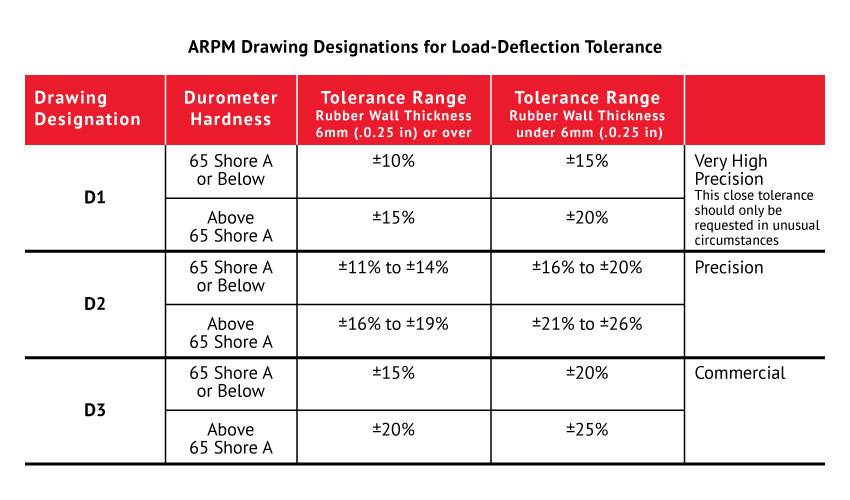
Methods of Designating Static and Dynamic Tolerances
When applicable, the design engineer must specify method of test, spring rate, and load deflection along with associated tolerances. If damping characteristics are required as a part of a dynamic specification, commercial tolerances would be ±25% on parts up through 65 durometer hardness (SHORE A) and ±30% for parts above 65 durometer hardness (SHORE A).
 Special Considerations for Static and Dynamic Load Deflection of Urethane Parts
All the aforementioned considerations are applicable to urethane parts with hardness on the SHORE A scale.
Access more articles in our Rubber Knowledge Center and our Urethane Knowledge Center.